How Do Prefabricated Vertical Drains Work? Wick Drains and Soft Ground Consolidation Explained
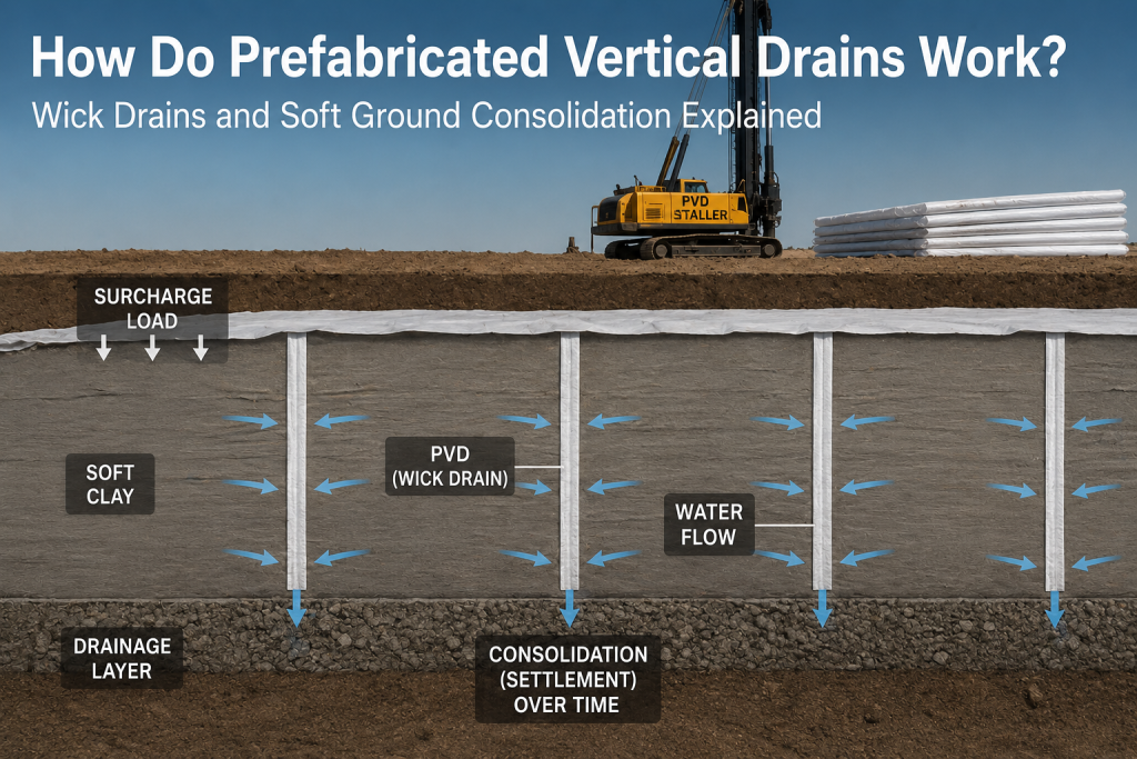
Soft, saturated soils — such as marine clays, estuarine deposits and reclaimed land — are among the most challenging substrates encountered in civil engineering. They are compressible, weak, and slow to drain, meaning that structures built on them will settle over long periods and may experience stability problems during and after construction. Prefabricated Vertical Drains (PVDs), commonly known as wick drains or band drains, are one of the most effective and widely used geosynthetic solutions for accelerating the consolidation of these difficult ground conditions. This article explains the engineering principles behind PVDs, how they are installed, and what they achieve.
The Problem: Why Soft Ground Is Difficult to Build On
A saturated soft clay soil contains a large volume of water held within its void spaces. When a load is applied to such a soil — through an embankment, a building foundation, or a fill surcharge — the load is initially carried by the pore water rather than the soil skeleton. This is because water is much less compressible than the soil particles can rearrange themselves.
Over time, the excess pore water pressure created by the applied load drives water out of the soil voids. As the water drains, the load is progressively transferred to the soil particle structure, and the soil consolidates — meaning it compresses and gains strength. This time-dependent process is called ‘primary consolidation’ and is described mathematically by Terzaghi’s consolidation theory.
The fundamental problem with soft clays is that their hydraulic conductivity (permeability) is extremely low — typically in the range of 10⁻⁹ to 10⁻¹⁰ m/s. This means water takes a very long time to escape from a thick clay layer. For a 10-metre thick clay deposit consolidating through vertical drainage alone, the time to achieve 90% consolidation might be 20–50 years. This is entirely impractical for construction projects.
The Solution: Prefabricated Vertical Drains
PVDs solve this problem by dramatically shortening the drainage path that pore water must travel. Instead of draining vertically through the full thickness of the clay layer to a drainage boundary at the surface or base, water needs only to travel horizontally (radially) to the nearest PVD — a distance that is typically only 1.0 to 1.5 metres.
Because the time for consolidation is proportional to the square of the drainage path length, reducing the drainage path from 10 metres (vertical) to 1 metre (horizontal to the drain) reduces the consolidation time by a factor of approximately 100. This means that consolidation which would take decades can be achieved in months.
This principle — reducing drainage path length to accelerate consolidation — was first implemented using sand drains in the early 20th century. PVDs replaced sand drains from the 1970s onwards because they can be installed much more rapidly, are more economical, and their performance is more reliable.
What Is a Prefabricated Vertical Drain?
A PVD consists of two components: a plastic drainage core and a surrounding geotextile filter jacket.
The drainage core is a grooved or channelled strip of polypropylene or polyethylene, typically 100 mm wide and 4–6 mm thick. Its geometry — with longitudinal channels running along its length — is designed to provide high hydraulic capacity for water flow in the vertical direction, from the point of water entry at the core surface to the discharge point at the top of the drain.
The geotextile filter jacket surrounds the core on all sides. It performs the filtration function: allowing water to pass freely from the surrounding clay into the drainage channels of the core, while retaining clay particles and preventing them from entering the core and blocking the drainage channels (a process known as ‘filter clogging’). The geotextile must be designed with an Apparent Opening Size matched to the grain size of the soil being drained.
The complete PVD strip — core plus jacket — is typically 100 mm wide, 4–6 mm thick, and is supplied in rolls of up to 300 metres or more. The product is sometimes referred to as a ‘band drain’ from its ribbon-like geometry.
How Are PVDs Installed?
PVD installation is carried out by purpose-built crawler-mounted installation rigs. The key steps are as follows:
Step 1: Preparing the Working Platform
A granular working platform — typically 500–800 mm of compacted sand or gravel — is placed over the surface of the soft ground before PVD installation begins. This platform serves two purposes: it provides a stable working surface for the installation rig, and it acts as a horizontal drainage blanket through which the water expelled by the PVDs can flow to the perimeter of the treatment area for disposal.
Step 2: Threading the Drain into the Mandrel
The PVD strip is threaded through a hollow steel lance known as the mandrel, which has a rectangular cross-section slightly larger than the drain. An anchor plate or anchor rod is attached to the base of the drain, protruding below the mandrel tip. When the mandrel is pushed into the ground, the anchor holds the drain in place when the mandrel is subsequently withdrawn.
Step 3: Pushing the Mandrel into the Ground
The installation rig uses a static push or vibratory hammer to drive the mandrel to the required installation depth — typically to the base of the soft clay layer or to a firm stratum. As the mandrel penetrates, it displaces soil laterally. This lateral displacement disturbs and remoulds a thin zone of clay immediately adjacent to the mandrel — known as the ‘smear zone’. The smear zone has reduced permeability and somewhat reduces PVD performance in practice; this effect is accounted for in design calculations.
Step 4: Withdrawing the Mandrel
With the mandrel at the required depth, the installation rig withdraws the mandrel while the anchor plate holds the drain in place. The PVD remains in the ground, and the drain is cut at the surface and folded into the drainage blanket above. The rig then moves to the next installation point.
A typical installation rig can install 2,000–4,000 linear metres of PVD per day, making it practical to treat large areas in short timeframes.
The Drainage and Consolidation Process
Once installed, PVDs begin working immediately. As the surcharge load is applied above (typically a fill embankment), excess pore water pressure builds up in the clay. This pressure drives pore water radially outward toward the nearest PVD. The water enters the geotextile jacket, passes into the drainage channels of the core, and flows upward along the drain to discharge into the horizontal drainage blanket at the surface.
The process continues until the excess pore water pressure has largely dissipated — at which point the soil has consolidated, compressed, and gained strength. Settlement and strength gain are monitored using settlement gauges and piezometers installed throughout the treatment area, allowing engineers to confirm that the required degree of consolidation has been achieved before construction of the permanent structure proceeds.
Design Considerations for PVD Systems
The design of a PVD scheme involves determining the drain spacing, installation depth, surcharge height and duration required to achieve the target degree of consolidation within the available construction programme. Key design parameters include:
Drain spacing: PVDs are typically installed on a square or triangular grid pattern at 1.0–1.5 metre centres. Closer spacing reduces the drainage path further, accelerating consolidation.
Installation depth: Drains should penetrate to the base of the compressible layer or to a permeable stratum that can accept the discharged water.
Drain discharge capacity: The geotextile jacket and drainage core must be capable of transmitting the required flow without restricting drainage, particularly under the lateral stress imposed by the surrounding soil.
Design methods: The Barron (1948) and Hansbo (1981) analytical solutions are most widely used to calculate the time-settlement relationship for a PVD-treated deposit. Modern numerical finite element analysis is used for complex projects.
Where Are PVDs Used?
PVDs are applied wherever soft, compressible soils must be improved to allow construction within an acceptable timeframe. Common applications include: port and harbour land reclamation projects; highway embankments over soft ground; rail infrastructure on coastal lowlands; airport runway construction on estuarine deposits; and land development on formerly tidal or lacustrine areas.
Summary
Prefabricated Vertical Drains are among the most powerful tools available for accelerating the consolidation of soft ground. By reducing the drainage path length from the full clay thickness to approximately one metre — the radial distance to the nearest drain — PVDs can reduce consolidation times from decades to months. Their combination of rapid installation, reliable performance and cost-effectiveness has made them the dominant method for soft ground improvement in major infrastructure projects worldwide.
Comments & Questions
Be the first to add a useful question, correction or project-related observation.