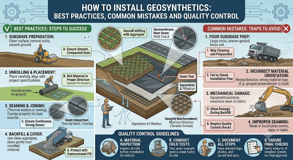
The performance of any geosynthetic material in service depends not only on its specified properties and correct design application but equally on the quality of its installation. A geotextile with excellent filtration properties that is damaged during placement over a rough subgrade, a geomembrane with inadequate seam quality, or a geogrid deployed with insufficient overlap at panel joints — all will underperform relative to their design intent, sometimes catastrophically. Unlike above-ground structural materials, geosynthetics are buried and inaccessible once construction is complete: installation errors cannot be easily identified or remedied after the fact. This article explains the key principles of correct geosynthetic installation, the most common mistakes made on site, and how quality control during installation protects the long-term performance of the geosynthetic system.
General Principles That Apply to All Geosynthetic Installation
Before any geosynthetic is unrolled, several site preparation requirements must be met. The subgrade on which the geosynthetic will be placed must be graded to the design profile, free from sharp protrusions — stones larger than the specified maximum particle size, tree roots, construction debris — that could puncture or damage the material. For geomembranes, subgrade preparation is especially critical: the prepared surface should pass a ‘boot test’, where walking across it in standard work boots leaves no impression that would concentrate stress on the membrane.
Material handling before and during installation must protect geosynthetics from damage. Rolls should be stored upright or on proper support frames, shielded from prolonged UV exposure and protected from mechanical damage by plant. Rolls should never be dropped from height, dragged over sharp surfaces or left submerged in standing water for extended periods before installation. Each roll should be inspected on delivery and before deployment for manufacturing defects, shipping damage and correct product identification against the delivery documentation.
Temperature affects installation practice for some geosynthetics. HDPE geomembranes expand and contract significantly with temperature change — thermal expansion coefficients are approximately 1.5 mm per metre per 10°C for HDPE. Geomembranes deployed in hot sun will be taut when they cool overnight; those deployed in cold conditions will wrinkle when warmed. Allowance for thermal movement must be made during panel deployment to avoid excessive stress at seams and anchor points.
Geotextile Installation: Key Steps and Requirements
Subgrade Preparation and Deployment
Geotextile rolls are deployed perpendicular to the direction of fill placement where possible, minimising the length of seams parallel to the direction of construction traffic. Rolls are unrolled by walking or driving the roll end along the prepared subgrade — never by pulling the tail of the roll, which stretches the fabric and can tear it at the roll core. On steep slopes, rolls are deployed from the crest downward, with the roll anchored at the top to prevent uncontrolled rollout.
The deployed geotextile must lie flat against the subgrade surface without folds, wrinkles or bridging across irregularities. Folds concentrate stress and create potential failure planes; bridging across hollows leaves unsupported spans that can tear under construction loading. On rough or irregular subgrades, a thin layer of sand blinding may be placed before the geotextile to provide a smooth surface and prevent puncture.
Seaming and Overlaps
Adjacent geotextile panels are joined either by sewing (sewn seams) or by overlapping (overlapped seams), depending on the application requirements. Sewn seams provide higher joint efficiency — the seam strength as a percentage of the intact fabric tensile strength — and are required where the geotextile must transmit tensile forces across the seam (reinforcement applications). They are made using portable industrial sewing machines with UV-stabilised polyester or polypropylene thread of equivalent durability to the parent fabric.
Overlapped seams — where adjacent panels are simply lapped over each other by a defined minimum width — are used where the primary function is separation or filtration rather than load transfer. Minimum overlap widths depend on the application: 300 mm is typical for separation geotextiles in road construction, increasing to 500–1000 mm or more in soft ground conditions where differential settlement may reduce effective overlap. Overlaps must always be laid so that the upper panel overlaps in the direction of fill placement — never under-lapped, which allows fill to wedge between the panels and lever them apart.
Protection During Fill Placement
The most common cause of geotextile damage after deployment is inadequate protection during fill placement and compaction. Construction plant — especially tracked machinery — should never operate directly on a deployed geotextile without a minimum protective cover of granular fill. The required minimum cover depth before trafficking depends on the machine weight and ground bearing pressure, but 150–300 mm of granular fill is a typical minimum.
Fill must be placed in a direction away from free edges of the geotextile, not toward them — otherwise the fill pushes the geotextile laterally, creating tension and potential tearing at anchor points. Fill placement equipment should not make sharp turns on thin geotextile cover layers.
Geogrid Installation: Critical Considerations
Orientation and Panel Layout
Uniaxial geogrids — which have high tensile strength in one direction only — must be deployed with the high-strength direction perpendicular to the anticipated loading direction. For retaining wall reinforcement, this means the high-strength direction runs horizontally into the fill, perpendicular to the wall face. For road base reinforcement with uniaxial geogrids, the strong direction runs across the road, perpendicular to the direction of traffic. Incorrect orientation of a uniaxial geogrid can result in deployment of near-zero reinforcement stiffness in the critical loading direction.
Biaxial and triaxial geogrids provide stiffness in multiple directions and are less orientation-sensitive, but even these products should be deployed with their machine direction clearly identified and recorded for the as-built record.
Joints and Connections
Adjacent geogrid panels are connected using bodkin bar connections (a transverse bar threaded through the apertures of both panels and locked in place), mechanical connectors, or — for less structurally critical applications — simple overlapping by one to two aperture widths. Bodkin connections provide efficient tensile load transfer between panels and are the standard connection method in reinforced soil wall and steep slope construction. Connection efficiency — the proportion of the geogrid tensile strength that can be transferred across the connection — varies between connection types and must be confirmed by testing.
Compaction Without Damage
Geogrids are vulnerable to damage from compaction plant operating directly on them before adequate fill cover is in place. Vibrating compaction plant should not be operated within the minimum cover depth specified by the designer — typically 150–200 mm for light vibratory rollers on biaxial geogrids, increasing for heavier plant. The angular edges of rib junctions can concentrate stress and cause tearing if a heavy vibratory roller passes over a geogrid in direct contact with a firm subgrade.
Geomembrane Installation: The Most Demanding Geosynthetic Deployment
Panel Deployment and Thermal Management
HDPE geomembrane panels are typically 7–8 metres wide and up to 200 metres long, and are deployed using specialised equipment — a panel deployment vehicle or crane-suspended roll spreader — to minimise foot traffic on the membrane surface. Workers wear soft-soled shoes when walking on the membrane. Panels are laid in the direction that minimises seam lengths running perpendicular to the slope direction — transverse slope seams experience higher tensile stress than longitudinal seams and are minimised where possible.
As noted above, thermal expansion and contraction must be managed during deployment. Panels deployed in cool morning temperatures will develop slack as they warm during the day. This slack must be managed to prevent excessive wrinkling, which concentrates stress at fold lines during subsequent fill placement. Conversely, panels deployed in the heat of the day must be allowed for length change as temperatures drop, or panels will go into tension across anchor points overnight.
Welding and Seam Quality
All geomembrane seams are thermally welded — by hot wedge (dual-track fusion weld) or extrusion fillet weld — by certified, experienced welding technicians using calibrated welding equipment. Pre-weld surface preparation — grinding away the oxidised surface layer of HDPE to expose fresh material — is essential for HDPE; skipping this step results in seams with inadequate fusion strength. Welding machine settings (temperature, pressure, speed) must be verified by trial welds tested to the specified peel and shear criteria before production welding commences each day and after any interruption or equipment change.
All seams are 100% non-destructively tested — air channel pressure testing for double-track seams, vacuum box or spark testing for extrusion welds — and destructive coupon tests taken at a defined frequency (typically 1 per 150 metres of seam or per working shift, whichever is more frequent). Any defect found must be marked, documented, repaired and re-tested before fill placement proceeds over that seam location.
Common Installation Mistakes and Their Consequences
Insufficient overlap: Overlaps that are too narrow — from cost-cutting or inattention — are the most common geotextile installation error. Under differential settlement or lateral soil movement, a 150 mm overlap may reduce to zero, leaving an unprotected gap through which soil particles migrate.
Incorrect orientation of uniaxial geogrid: Deploying the low-stiffness direction perpendicular to the load effectively provides no reinforcement in the critical direction. This error has caused retaining wall face deformations and slope failures.
Skip-testing geomembrane seams: Any seam not tested is an unknown risk. The effort saved by skipping seam testing is trivial compared to the cost of locating and repairing a leaking seam after fill placement.
Driving on geomembranes without cover: A single passage of tracked plant over an unprotected geomembrane on a hard subgrade will leave stress cracks and potential punctures that may not be immediately visible but will propagate under sustained hydraulic pressure.
Ignoring UV exposure limits: Leaving geotextile exposed beyond the manufacturer’s recommended maximum time — sometimes weeks on a large site — causes measurable strength loss before the material is even in service.
Summary
Correct installation is as important as correct specification in determining the long-term performance of geosynthetic systems. Key principles — proper subgrade preparation, correct deployment direction and orientation, adequate overlaps or sewn seams, protection from construction plant before adequate cover is in place, 100% seam testing for geomembranes, and strict UV exposure management — apply across all geosynthetic types. Comprehensive documentation of installation procedures, material batch identification and quality test results creates an as-built record that is invaluable for future maintenance, performance assessment and any remediation that may be required. Installation quality is the bridge between excellent specification and reliable long-term performance.